|
 Gas Discharge Overview Gas Discharge Overview  |
Protection for PC Board Level Components
Today’s microprocessor based electronic equipment are increasingly more vulnerable to lightning induced voltage surges and electrical switching transients because they have become more sensitive, and complex to protect due to their high chip density, binary logic functions and connection across different networks. These devices are critical to a company’s communications and information processing and typically can have an impact on the bottom line; as such it is prudent to insure them against these potentially costly and disruptive events. A Gas Discharge Tube or GDT can be used as a standalone component or combined with other components to make a multistage protection circuit – the gas tube acts as the high energy handling component.
GDT’s are typically deployed in the protection of communication and data line DC voltage applications because of its very low capacitance. However, they provide very attractive benefits on the AC power line including no leakage current, high energy handling and better end of life characteristics.
GAS DISCHARGE TUBE TECHNOLOGY
The gas discharge tube may be regarded as a sort of very fast switch having conductance properties that change very rapidly, when breakdown occurs, from open-circuit to quasi-short circuit (arc voltage about 20V). There are accordingly four operating domains in the behavior of a gas discharge tube: |
 |
The GDT may be regarded as a very fast acting switch having conducting properties that change very rapidly when breakdown occurs and transforms from an open-circuit to a quasi-short circuit. The result is an arc voltage of about 20V DC. There are four stages of operation before the tube fully switches. |
|
- Non-operating domain: Characterized by practically infinite insulation resistance.
- Glow domain: At the breakdown, the conductance increases suddenly. If the current is drained off by the gas discharge tube is less than about 0.5A (rough value that differs from component to component) , the glow voltage across the terminals will be in the 80-100V range.
- Arc regime: As the current increases, the gas discharge tube shifts from glow voltage to the arc voltage (20V). It is this domain that the gas discharge tube is most effective because the current discharge can reach several thousand amperes without the arc voltage across the terminals increasing.
- Extinction: At a bias voltage roughly equal to the glow voltage, the gas discharge tube covers to its initial insulating properties.
|
 3-Electrode Configuration 3-Electrode Configuration |
Protecting a two-wire line (for example a telephone pair) with two 2-electrode gas discharge tubes may cause the following problem:
If protected line is subjected to an overvoltage in the common mode, the dispersion of the sparkover voltages (+/- 20%), one of the gas discharge tubes sparks over a very short time before the other (typically a few microseconds), the wire that has the sparkover is therefore grounded (neglecting the arc voltages), turning the common-mode overvoltage into a differential mode overvoltage. This is very dangerous for the protected equipment. The risk disappears when the second gas discharge tube arcs over (a few microseconds later).
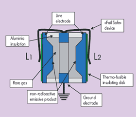
The 3-electrode geometry eliminates this drawback. The sparkover of one pole causes a general breakdown of the device almost immediately (a few nanoseconds) because there is only one gas filled enclosure housing all the effected electrodes. |
End of Life
The gas discharge tubes are designed to withstand many impulses without destruction or loss of the initial characteristics (typical impulse tests are 10 times x 5kA impulses for each polarity).
On the other hand, a sustained very high current, i.e. 10A rms for 15 seconds, with simulate the dropping out of the AC power line onto a telecommunication line and will take the GDT immediately out of service.
If a fail-safe end of life is desired, i.e. short circuit that will report a fault to the end user when the line fault is detected, the gas discharge tube with the fail-safe feature (external short-circuit) should be selected. |
Selecting a Gas Discharge Tube
The information required to properly select a surge protector for your application is the following:
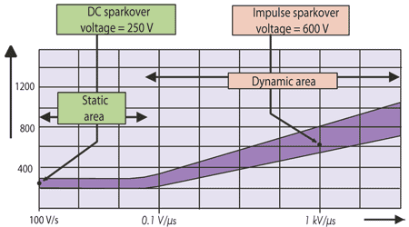
- DC sparkover voltage (Volts)
- Impulse sparkover voltage (Volts)
- Discharge current capacity (kA)
- Insulation resistance (Gohms)
- Capacitance (pF)
- Mounting (Surface Mount, Standard Leads, Custom Leads, Holder)
- Packaging (Tape & Reel, Ammo pack)
Range of DC sparkover voltage available:
- Minimum 75V
- Average 230V
- High Voltage 500V
- Very High Voltage 1000 to 3000V
*Tolerance on the breakdown voltage is generally +/-20% |
 |
Discharge Current
This depends on the properties of the gas, the volume and the material of the electrode plus its treatment. This is the major characteristic of the GDT and the one that distinguishes it from the other protection device, i.e. Varistors, Zener Diodes, etc… Typical value is 5 to 20kA with an 8/20us impulse for standard components. This is the value the gas discharge tube can withstand repeatedly (minimum 10 impulses) without the destruction or alteration of its basic specifications.
Impulse Sparkover Voltage
The sparkover voltage in the presence of a steep front (dV/dt = 1kV/us); the impulse sparkover voltage increases with the increasing dV/dt.
Insulation Resistance and Capacitance
These characteristics make the gas discharge tube practically invisible during normal operating conditions. The insulation resistance is very high (>10 Gohm) while the capacitance is very low (<1 pF).
STANDARDS
Test Standards and installation recommendations for communication line surge protectors must comply with the following standards:
- UL497B : Protectors for Data Communications and Fire-Alarm Circuits
INSTALLATION
To be effective, the surge protector must be installed in accordance with the following principles.
- The ground point of the surge protector and of the protected equipment must be bonded.
- The protection is installed at the service entrance of the installation to divert impulse current as soon as possible.
- The surge protector must be installed in close proximity, less than 90 feet or 30 meters) to protected equipment. If this rule cannot be followed, secondary surge protectors must be installed near to the equipment
- The grounding conductor (between the earth output of the protector and the installation bonding circuit) must be as short as possible (less than 1.5 feet or 0.50 meters) and have a cross sectional area of at least 2.5 mm squared.
- The earth resistance must adhere to the local electrical code. No special earthing is necessary.
- Protected and unprotected cables must be kept well apart to limit coupling.
MAINTENANCE
CITEL gas discharge tubes require no maintenance or replacement under normal conditions. They are designed to withstand repeated, heavy duty surge currents without damage.
Nevertheless, it is prudent to plan for the worst case scenario and, for this reason; CITEL has designed for the replacement of protection components where practical.
The status of your data line surge protector can be tested with CITEL’s model SPT1003. This unit is designed to test for the DC sparkover voltage, clamping voltages and line continuity (optional) of the surge protector. The SPT1003 is a compact, push button unit with a digital display. The voltage range of the tester is 0 to 999 volts. It can test individual components such GDT’s, diodes, MOVs or stand alone devices designed for AC or DC applications.
SPECIAL CONDITIONS: LIGHTNING PROTECTION SYSTEMS
If the structure to be protected is equipped with a LPS (Lightning Protection System), the surge protectors for telecom , data lines or AC power lines that are installed at the buildings service entrance need to be tested to a direct lightning impulse 10/350us wave form with a minimum surge current of 2.5kA (D1 category test IEC-61643-21).
|
| |
| |
| |
CITEL INC. 10108 USA Today Way | Miramar, FL 33025 USA | Toll Free 800.248.3548 | Tel: 954.430.6310| Fax 954.430.7785
|


